$272Basic 


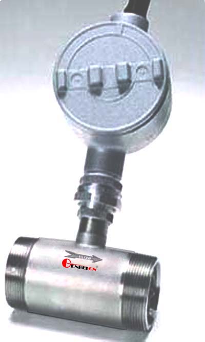
Geenbellon Turbine Flow Meters can measure fowing medium in a closed pipe system and display flow rate and total flow in Volume unit in same time. the theory of this type flow meter is that the flowing medium engages a vaned rotor causing it to rotate at an angular velocity proportional to the flow rate Within the turbine flow meter. The pickup coil senses the spinning motion of the rotor through the housing and converts it into a pulsing electrical signal. Totalling the pulsing electrical signal directly yields to the total flow, while the frequency is linearly related to the flow rate.
The flow meter is featured that it is tough for an applications in severe condition with high accuracy, light weight, interface flexible, anti-abrasion, and anticorrosion. So, it is applied widely in industry, Municipal, Agriculture, Military engineering. The production introduced as below is one of all models.
Features
<> ±1% of Reading Accuracy
<> Ball Bearing Design for Economy
<> 440C Bearing Retainers for Durability
<> Ball Bearings Field Replaceable Without Loss of Calibration
<> Deflector Cones Stabilize Low Mass Rotor for Increased Bearing Life
<> NIST Certificate Supplied Standard
Applications
1. Industry Engineering
2. municipal Engineering
e.g Air, gas, alkenes, alkynes, sulfur dioxide, carbon monoxide, carbon dioxide, oxygen, nitrogen, hydrogen, chlorine gas, methane
The turbine gas flow meters are designed to measure actual cubic feet or actual volume passing through the meter. Before sizing a flowmeter, it is necessary to convert flow units (i.e., SCFM, LPM, etc.) to actual units. To convert to actual measured volume (ACFM) from standard volume (SCFM), use the following formula: ACFM = SCFM x 14.7/Pa x Ta/530
where:
ACFM = Actual cubic feet per minute of measured gas flow
SCFM = Standard cubic feet per minute gas flow
Pa = Operating pressure (psia) in = (psig + 14.7)
Ta = Temperature in degrees, Rankine = (°F + 460)
Related Document
 GIL-Products-List Model-Selecting-Sheet