SPECIFICATIONS
PERFORMANCE SPECIFICATIONS
Fluid to be Measured: Liquid, gas,
steam (avoid multiphase flow and
sticky fluids)
Measuring Flow Rates:
Refer to Table 6
Accuracy: ?.75% of reading (liquid),
?% of reading (gas, steam). Refer to
Table 5
Repeatability: ?.2% of reading
Calibration: Factory-calibrated using
water flow
NORMAL OPERATING CONDITION
Process Temperature Range:
General: -40 to 260�C
(-40 to 500�F)
High Process Temperature
Version Option (-HT): -40 to 450�C
(-40 to 842�F). Refer to Fig. 1 for
integral converter type
Process Pressure Limit: -14.2 PSIA
(-1 kg/cm2) to flange rating
Ambient Temperature Range:
Remote Type Detector, Remote
Type Converter: -40 to 85�C
(-40 to 185�F)
Integral Type (Refer to Fig. 1):
-40 to 85�C (-40 to 185�F)
Integral Type with Indicator
(Refer to Fig. 1): -30 to 80�C
(-22 to 176�F)
Ambient Humidity: 5 to 100% RH
[at 40�C (104�F)] (non-condensing)
Power Supply Voltage: 10.5 to
42 Vdc (refer to Fig. 2, �Relationship
Between Power Supply Voltage and
Load Resistance.?
MECHANICAL SPECIFICATIONS
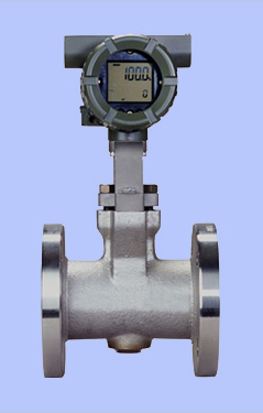
Material (General Type):
Body: CF8M casting stainless
steel (SUS316)
Shedder Bar: Duplex stainless
steel (ASTM CD4MCu equivalent
to JIS SUS329J1). -HT option has
Hastelloy C
Gasket: JIS SUS316 stainless steel
with polytetrafluoroethylene
(Teflon? coating.
Converter Housing and
Case, Cover: Aluminum alloy
Coating Color: Converter case
and cover are deep sea moss green
(Munsell 0.6GY 3.1/2.0)
(Polyurethane corrosionresistance
coating)
Protection: NEMA 4X (IP67)
immersion proof and dust proof
Electrical Connection:
ANSI 1⁄2" NPT female
Signal Cable: Cable used for remote
detector and converter
Max. Length: 30 m (98')
Outer Sheath Material:
Heat-resistant polyethylene
Temperature Rating: -40 to 150�C
(-40 to 302�F)
Weight: Refer to
dimensional drawings
Mounting:
Integral Type and Remote Type
Detector: Flange mounting or
wafer mounting
Remote Type Converter:
2" pipe mounting
ELECTRICAL SPECIFICATIONS
Note: Pulse output, alarm output and
status output use common terminals,
therefore, these functions are not
used simultaneously
Output Signal: Simultaneous output
(both analog and transistor contact
output available). Refer to
�Installation?for power supply and
pulse output wiring
Analog:
4 to 20 mA DC, 2-wire system
Transistor Contact Output:
Open collector, 3-wire system.
Pulse, alarm, status output are
selected by parameter setting.
Contact Rating: 30 Vdc,
120 mA DC
Low Level: 0 to 2 Vdc
(refer to Fig. 3)
Communication Requirement:
Conditions of Communications
Line: 250 to 600 (including cable
resistance), refer to Fig. 2
Supply Voltage: 16.4 to 42 Vdc;
refer to Fig. 2
Spacing from Power Lines:
15 cm (6") or more (parallel wiring
should be avoided)
Display Unit: %, I, t, Nm3, m3, kg scf,
cf, gal, lb, /h, /m
Cable Length for Specific
Applications: Use the following
formula to determine cable length for
specific applications:
L= 65 x 106 _ (Cf + 10,000)
(R x C) C
where:
L=length in meters
R=resistance in
(including barrier resistance)
C=cable capacitance in pF/m
Cf=maximum shunt capacitance
of receiving devices in pF/m